Compare two-tier, three-tier, spine-leaf, WAN, SOHO, on-premises, and cloud designs.
Select copper, multimode fiber, or single-mode fiber for a stated requirement.
Use interface counters to recognize speed, duplex, collision, and cabling problems.
Introduction
Every network, whether it belongs to a small office,
a retail store, a university, a data center, or a multinational enterprise, is
built from several different types of devices.
A computer alone cannot communicate with a server in
another building or reach an application on the Internet. Multiple network
devices work together to move the traffic from the source to the destination.
Consider what happens when an employee opens a web
browser and connects to a company application hosted in a data center.
The traffic may travel through:
Downstream to Upstream traffic flows path
Each device has a specific responsibility.
The access switch connects the PC to the local
network. The Layer 3 switch moves traffic between VLANs and IP networks. The
firewall applies security policies. The router determines how to reach remote
networks. The server provides the application requested by the user.
Understanding these roles is one of the most
important foundations of networking.
In this lesson we will study the following network
components:
Routers
Layer 2 switches
Layer 3 switches
Next-generation firewalls
Intrusion prevention systems
Wireless access points
Wireless and network controllers
Endpoints
Servers
Power over Ethernet
Network components and hierarchy
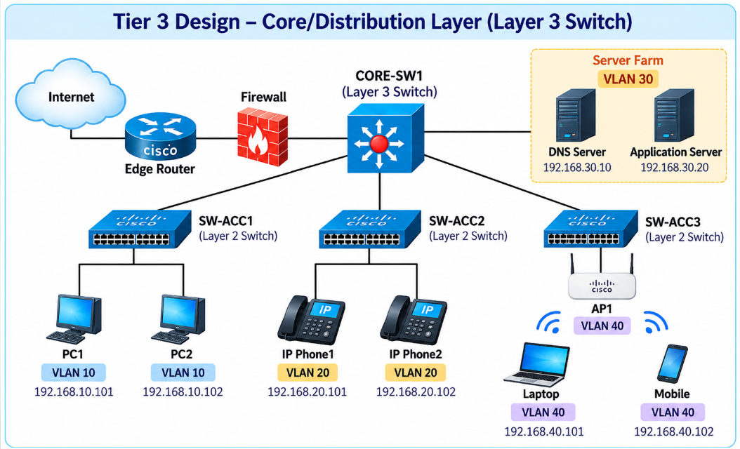
We will use the following networks:
Function
VLAN
Network
User Network
10
192.168.10.0/24
Voice Network
20
192.168.20.0/24
Server Network
30
192.168.30.0/24
Wireless Network
40
192.168.40.0/24
Management Network
99
192.168.99.0/24
Example addressing:
PC1192.168.10.101
PC2192.168.10.102
IP Phone192.168.20.101
DNS Server192.168.30.10
Application Server192.168.30.20
Wireless Laptop192.168.40.101
WLC192.168.99.20
Default gateways are configured on the Layer 3 core
switch.
We will keep returning to this topology as we discuss
each component.
1. What Is a Router?
A router is a
network device that connects two or more different IP networks and forwards
packets from one network to another.
A router primarily operates atLayer 3 — the Network layer — of the OSI model.
Its main forwarding decision is based on the destination IP address contained
in an IP packet.
For example, consider two networks:
Network A: 192.168.10.0/24
Network B:192.168.20.0/24
A host in
Network A cannot directly communicate with a host in Network B because they
belong to different IP networks. A Layer 3 device, such as a router, is
required to move traffic between them.
Figure 1: Working of Routers
Why Do We Need a Router?
Without
Router R1, the two networks are separate.
A Layer 2
switch can forward frames inside a Layer 2 network or VLAN, but it does not
normally route traffic between different IP networks.
The
router provides the Layer 3 connection.
A useful
way to remember this is:
Switches connect devices within a
LAN. Routers connect different IP networks.
Later,
you will learn that a Layer 3 switch can
also perform routing, but the basic routing principle remains the same.
What Information Does a Router Use?
A router
primarily examines the:
Destination IP address
It then
compares that address against entries in its:
Routing table
The
router determines:
What
destination network does this IP belong to?
Do I have a route to that
network?
Which interface or next-hop
router should I use?
Where should the packet be
forwarded?
Key Point
A router: connects different IP networks, examines destination
IP addresses, consults its routing table, selects an outgoing path, and
forwards packets toward their destination.
2. Layer 2 and Layer 3 Switches
Switches
are fundamental devices in almost every modern LAN. They connect computers, IP
phones, printers, wireless access points, servers, cameras, and many other
devices.
However,
not all switches perform exactly the same job.
A Layer 2 switch primarily forwards Ethernet
frames by using MAC addresses, while a Layer 3 switch can perform Layer 2 switching
and also route traffic between different IP networks or VLANs. This distinction
is already established in the Module 1 material.
2.1 What Is a Layer 2 Switch?
A Layer 2 switch is a multiport
device that forwards Ethernet frames based on the destination MAC address. It
builds and maintains a MAC address table (also called a CAM table) by learning
which MAC address is reachable on which physical port.
How a
Layer 2 Switch Works
1.Learn — When a frame enters a port, the switch
records the source MAC address and the port it arrived on in its MAC
address table.
2.Flood— If
the destination MAC address is not yet in the table, the switch floods the
frame out of every port except the one it arrived on.
3. Forward—
Once the destination MAC address is known, the switch forwards the frame
only out of the correct port (this is called filtering).
4. Age Out—
Entries that are not refreshed within the aging time (default 300 seconds
on Cisco IOS) are removed from the table.
MAC
addresses
It does
not normally examine the destination IP address to decide which access port
should receive a normal Ethernet frame.
A Layer 2
switch is commonly used to connect:
Desktop computers
Laptops
IP phones
Printers
Wireless access points
Cameras
Point-of-sale systems
IoT devices
Other switches
Topology: Access layer design
Key
Characteristics of a Layer 2 Switch
Operates only at the Data Link Layer
(Layer 2).
Forwards frames using MAC addresses only —
it has no concept of IP subnets.
Every port in the same VLAN belongs to the
same broadcast domain.
Cannot route between VLANs or subnets on
its own — it needs an external router (e.g., router-on-a-stick) to do
that.
Typically, cheaper and used at the access
layer, connecting end devices like PCs, printers, and IP phones.
Limitation
to Remember
A pure Layer 2 switch CANNOT move traffic between
two different IP subnets/VLANs by itself. If PC-A (VLAN 10) needs to talk to
PC-C (VLAN 20), that traffic must be sent to a Layer 3 device (a router, or a
Layer 3 switch) for routing.
2.2 What Is a Layer 3 Switch?
A Layer 3 switch is a switch that
also has routing capability built in. In addition to a MAC address table, it
maintains a routing table and can route packets between VLANs/subnets using
hardware-based routing (ASICs), which makes it extremely fast — often as fast
as normal switching.
How a
Layer 3 Switch Works
Switched Virtual Interfaces (SVIs) — a
logical Layer 3 interface is created for each VLAN (e.g., interface vlan
10), and it is assigned an IP address that acts as the default gateway for
devices in that VLAN.
Routing Table — once IP routing is enabled
globally (ip routing), the switch builds a routing table just like a
router and can forward packets between the SVIs of different VLANs.
Hardware-Based (ASIC) Routing — unlike a
traditional router that routes in software/CPU, a Layer 3 switch routes
using dedicated hardware chips, so performance stays extremely high even
at full traffic load.
Topology: Tier 3 Design
Key Characteristics of a Layer 3 Switch
Combines Layer 2 switching and Layer 3
routing in a single device.
Uses SVIs (Switched Virtual Interfaces) as
gateway addresses for each VLAN.
Performs inter-VLAN routing internally, at
very high (wire) speed.
Commonly deployed at the distribution/core
layer of a campus network.
Usually does NOT support WAN interfaces
(like serial links) — that is still the job of a dedicated router.
Layer
2 vs Layer 3 Switch — Side-by-Side Comparison
Feature
Layer 2 Switch
Layer 3 Switch
OSI Layer
Data Link (Layer 2)
Data Link + Network (Layer 2 & 3)
Forwarding Decision
MAC address
MAC address AND IP address
Table Used
MAC address table (CAM table)
MAC address table + Routing table
Inter-VLAN Routing
No (needs external router)
Yes (built-in, via SVIs)
Broadcast Domains
One per VLAN (cannot cross)
One per VLAN, but can route between them
Speed of Routing
N/A
Very fast — hardware/ASIC based
WAN Interfaces
(Serial, etc.)
No
Typically no (still needs a router)
Typical Placement
Access layer
Distribution / Core layer
Relative Cost
Lower
Higher
Lesson Summary
A Layer 2 switch connects devices and forwards Ethernet
frames according to MAC addresses. It learns source MAC addresses,
maintains a MAC address table, forwards known unicasts, floods unknown
unicasts, handles broadcasts, and uses VLANs to create separate Layer 2
broadcast domains.
A Layer 3 switch provides all of those switching
capabilities and additionally routes IP packets between networks. It can
provide SVI default gateways, maintain a routing table, perform inter-VLAN
routing, and use routed physical interfaces.
The most important distinction for CCNA is:
Layer 2 switch = MAC-based switching
Layer 3 switch = MAC-based switching
+ IP routing
In an enterprise network, these technologies work
together: access switches connect endpoints, while Layer 3 switches
commonly provide routing between VLANs and upstream connectivity.
3. Next-Generation Firewalls and Intrusion Prevention
Systems
Security
devices sit between networks that have different levels of trust. For example,
an enterprise normally treats its internal user and server networks as more
trusted than the public Internet. A firewall is placed at this boundary so that
traffic can be inspected and controlled before it is allowed to cross from one
security zone to another.
Anext-generation firewall (NGFW)expands
traditional firewall capabilities by adding deeper inspection and security functions such as application awareness, user-aware policy, intrusion prevention, malware protection, URL filtering, and advanced threat inspection.
An Intrusion Prevention System (IPS)
analyzes traffic for signs ofmalicious activity and can actively block or
disrupt the attack. Your existing Module 1 content introduces the firewall as
the security boundary between theinternal network and the Internet and
describes these NGFW and IPS capabilities.
By the
end of this lesson, a learner should understand where an NGFW and IPS are
placed in an enterprise network, how stateful inspection works, how security
zones and policies control traffic, how an IPS differs from an IDS, and how to
approach common firewall- and IPS-related troubleshooting scenarios.
3.1 Next-Generation Firewall
What Is a Firewall?
A firewall is a security device that controls
traffic moving between networks or security zones.
A
firewall may be placed between:
An internal corporate network
and the Internet
User networks and a data
center
A branch office and a WAN
A DMZ and an internal network
A cloud network and an
on-premises network
The
firewall evaluates traffic against a configured security policy and determines
whether the connection should be ALLOW or DENY. The
fundamental purpose is not simply to "block the Internet." The
firewall allows required business communication while preventing traffic that
violates security policy.
3.2 Intrusion Prevention System
What Is an IPS?
IPS
stands for Intrusion Prevention System. An IPS
examines network traffic for signs of malicious activity. Its
purpose is not simply to decide whether TCP port 443 is permitted. Instead,
it can inspect the traffic more deeply and look for behavior or content
associated with threats.
Examples
might include:
Exploit attempts
Known attack signatures
Malware-related traffic
Protocol abuse
Suspicious payload patterns
Other policy-defined threat
indicators
If the
IPS identifies malicious activity, it may actively take action.
An IPS as
a system that analyzes traffic for malicious activity and lists actions such as
blocking packets, resetting sessions, generating alerts, logging the event, and
preventing communication.
IPS
actions may include ALLOW (if traffic is considered legitimate), ALERT (if the
event should be logged), DROP (if malicious packets should be discarded), BLOCK
(to prevent the connection) and RESET (to terminate an existing session). The
security administrator decides how different threat categories should be
handled.
The key
distinction is:
Firewall: Is this communication
allowed by policy?
IPS: Does this traffic appear
malicious, and should it be stopped?
In many
modern enterprise networks, both functions are integrated into the same NGFW
platform.
4. Wireless access points and Controllers (WLCs)
Wireless Access Points (WAPs/APs)
A wireless access point is a networking device that lets wireless
(Wi-Fi) devices connect to a wired network. It acts as a bridge between the
wired LAN (Ethernet) and wireless clients like laptops, phones, and tablets.
How it works:
The
AP connects to a switch via an Ethernet cable.
It
broadcasts a wireless signal (SSID) that client devices can detect and
join.
Once
connected, wireless devices can communicate with each other and reach
resources on the wired network (like servers) or the internet.
Key modes/deployment types:
Autonomous
AP (standalone) – Each AP is independently configured and managed. Fine
for small networks, but doesn't scale well since every AP needs individual
configuration.
Lightweight
AP (controller-based) – APs are managed centrally by a Wireless LAN
Controller (WLC). The controller pushes configuration, handles RF
management, and simplifies large deployments (common in enterprise
networks).
Related concepts:
SSID
(Service Set Identifier) – the network name broadcast by the AP.
BSS
(Basic Service Set) – one AP and its connected wireless clients.
ESS
(Extended Service Set) – multiple APs working together (often with the
same SSID) to provide continuous coverage across a larger area, allowing
roaming.
Placement consideration: APs need to be positioned for adequate
coverage and minimal interference, often requiring a site survey in larger
environments.
Wireless LAN Controllers (WLCs)
A WLC is
a centralized device that manages and controls multiple lightweight access
points across a network. Instead of configuring each AP individually, administrators configure settings once on the controller, and it pushes that
configuration out to all the APs it manages.
Why controllers exist:
In large
networks with many APs (offices, campuses, warehouses), managing each AP
separately (autonomous mode) becomes inefficient. Controllers solve this by
centralizing management.
What a WLC does:
Centralized
configuration –
SSIDs, security settings, and QoS policies are set once and pushed to all
associated APs.
RF (radio
frequency) management – Dynamically adjusts power levels and channels on APs to reduce
interference and optimize coverage.
Roaming
support– Allows
seamless client roaming between APs without dropping the connection, since
the controller tracks client associations across the network.
Security and
authentication –
Centralize management of authentication methods (e.g., WPA2/WPA3, 802.1X)
across all APs.
Monitoring
and troubleshooting
– Provide a single dashboard to view AP status, client connections, and
network health.
How APs communicate with a WLC:
Lightweight
APs use a protocol called CAPWAP (Control and
Provisioning of Wireless Access Points) to communicate with the
controller. CAPWAP tunnels both control traffic (management) and sometimes data
traffic between the AP and WLC.
Deployment models for controllers:
On-premises
hardware controller
– A physical WLC appliance located in the network.
Cloud-based
controller –
Management done through the cloud (e.g., Cisco Meraki, Cisco DNA Center),
reducing the need for on-site hardware.
Embedded/switch-based
controller – WLC
functionality built into a switch.
Exam-relevant distinction: Know that autonomous
APs = no controller needed (self-contained), while lightweight APs = require a
WLC to function fully, since they rely on it for configuration and
control-plane operations.
5. Endpoints,
Servers and PoE
End-User Devices
End-user
devices are the endpoints that people use to access and interact with the
network — they're the reason the network exists in the first place. For CCNA,
this topic is about recognizing these devices and understanding that they
connect to the network via NICs (Network Interface Cards), wired or wireless.
Common categories:
Computers – Desktops, laptops (connect
via Ethernet or Wi-Fi).
Mobile
devices–
Smartphones, tablets (typically wireless connections).
IP phones – VoIP devices that connect
to switches, often using a feature called a "voice VLAN" to
separate voice traffic from data traffic.
Printers/scanners – Network-attached
peripherals, wired or wireless.
IoT devices – Smart devices like
cameras, sensors, smart speakers, thermostats — increasingly common on
modern networks and often requiring special VLAN/security consideration.
How they connect:
Wired – Via Ethernet cable to a
switch port, using a NIC.
Wireless– Via a wireless NIC,
associating with an AP using an SSID.
Servers
A server
is a device (or software running on a device) that provides resources or
services to other devices on the network, called clients. Servers are the
"back end" of the network — where data, applications, and services
live.
How servers work:
Servers
operate on a client-server model: a
client sends a request, and the server responds with the requested resource or
service. Servers typically run specialized software and often have more
powerful hardware (CPU, RAM, storage) than end-user devices, since they handle
multiple simultaneous requests.
Common types of servers (know these for the exam):
File server – Stores and shares files
across the network.
Print server – Manages and queues print
jobs for network printers.
Web server – Hosts websites and
responds to HTTP/HTTPS requests.
DNS server– Translates domain names
(e.g., cisco.com) into IP addresses.
DHCP server – Automatically assigns IP
addresses and other network config to devices.
Mail server – Handles sending/receiving
email.
Application
server – Runs
business applications accessed by clients (e.g., databases, ERP systems).
Authentication
server (AAA) –
Handles login credentials and access control (e.g., RADIUS, TACACS+).
Placement in the network:
Servers
are usually located in a data center or server room, often connected to
core/distribution layer switches for high-speed, reliable access, rather than
sitting at the access layer like end-userdevices.
Power over Ethernet (PoE)
PoE is a
technology that allows a single Ethernet cable to carry both data and
electrical power to a connected device. This eliminates the need for a separate
power cable/outlet at the device location.
How it works:
A PoE-capable switch (or a
device called a PSE – Power Sourcing Equipment) injects DC power onto the
same twisted-pair copper cable used for data (typically Cat5e or higher).
The receiving device, called
a PD
(Powered Device),
draws power from the cable to operate.
Power and data travel
simultaneously without interfering with each other, using the unused pairs
or phantom power on the same pairs.
Common devices powered by PoE:
IP phones
Wireless access points
IP security cameras
IoT sensors
Some switches (in daisy-chain
setups)
PoE Standards:
Standard
Name
Max Power (at source)
802.3af
PoE
~15.4W
802.3at
PoE+
~30W
802.3bt
PoE++
(UPOE)
~60–100W
Why it matters (benefits):
Simplifies
installation –
no need for electrical outlets near devices like APs or cameras (useful
for ceiling-mounted equipment).
Cost savings – reduces cabling and
electrician labor.
Centralized
power management
– devices can be power-cycled remotely from the switch.
Supports UPS
backup – if the
switch is on a UPS, connected PoE devices stay powered during outages.
Exam-relevant terms:
PSE (Power
Sourcing Equipment) – the device supplying power (usually the switch).
PD (Powered
Device) – the
device receiving power (e.g., AP, IP phone).
6. Physical Interface and Cabling Types
6.1Single-Mode Fiber, Multimode Fiber, Copper
Fiber Optic Cabling (General)
Uses
light pulses (instead of electrical signals) transmitted through a glass or
plastic core to carry data. Immune to electromagnetic interference (EMI),
supports much longer distances and higher bandwidth than copper.
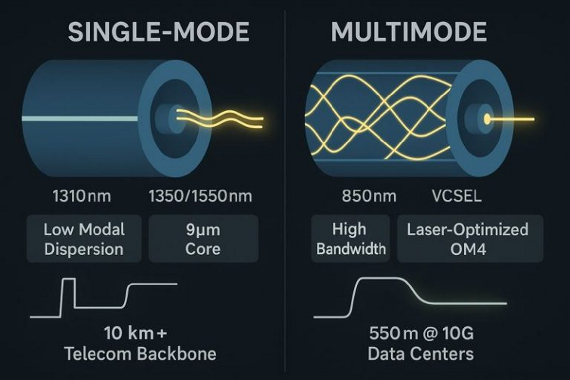
Single-Mode Fiber (SMF):
Has a small core (~9 microns), allowing only
a single
path (mode) of
light to travel straight down the fiber.
Uses a laseras the light source.
Supports very long
distances (up to
40+ km or more, depending on transceiver) with minimal signal
loss/distortion.
Cable is typically
color-coded yellow.
Use case: Long-haul connections —
between buildings, campuses, ISPs, WAN links, service provider backbones.
More expensive equipment
(lasers, precision connectors) but scales to very high speeds over
distance.
Multimode Fiber (MMF):
Has alarger core (50 or 62.5 microns),
allowing multiple light paths (modes) to travel simultaneously,
bouncing at different angles.
Uses an LED or VCSELas the light source (cheaper
than lasers).
Supports shorter
distances
(typically up to 300–550m, depending on standard) because multiple light
modes cause signal dispersion over distance.
Cable is typically
color-coded orange or aqua.
Use case: Shorter connections within a
building or data center — e.g., between switches on different floors, or
within a data center spine-leaf fabric.
Cheaper than single-mode for
short-range, high-bandwidth needs.
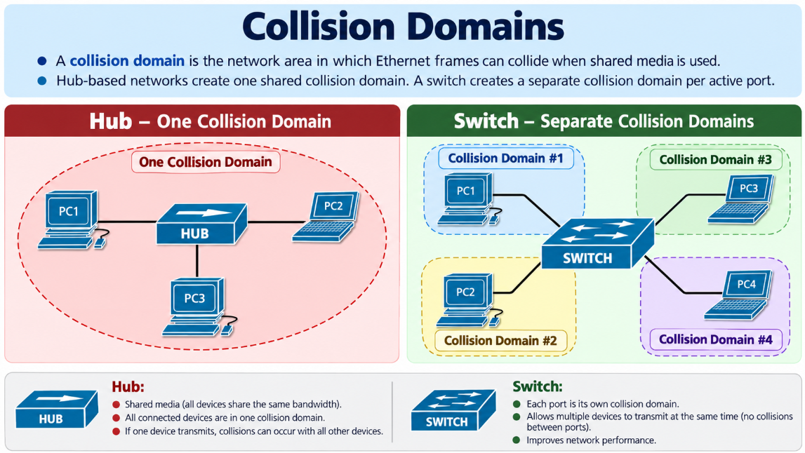
Multiple
devices share the same physical medium(cable/segment) to communicate, and only one device can transmit at a time
without causing a collision.
Details:
Historically used with hubsor older bus topologies
(e.g., coaxial Ethernet — 10BASE2/10BASE5) where all devices on a segment
shared one collision domain.
Devices use CSMA/CD (Carrier Sense Multiple
Access with Collision Detection) to manage access to the shared medium — a
device listens before transmitting, and if a collision occurs, both
devices back off and retransmit after a random delay.
Half-duplex communication — a device can
either send or receive at a time, not both simultaneously.
Largely obsolete in
modern wired networks since switches replaced hubs, but the concept still applies to wireless
(Wi-Fi) networks
— all devices on the same AP/channel share the same wireless medium and
must contend for airtime (using CSMA/CA — Collision Avoidance, since
wireless devices can't reliably detect collisions the way wired devices
can).
Feature
Point-to-Point
Shared Media
Devices
per segment
2
Multiple
Duplex
Full-duplex
Half-duplex
Collision
domain
Separate
per link
Shared
among all devices
Access
method
N/A
(dedicated)
CSMA/CD
(wired) / CSMA/CA (wireless)
Modern
example
Switch
ports, uplinks
Wi-Fi
(same AP/channel), old hubs
Exam-relevant point: Know that modern switchednetworks are point-to-point (each
switch port = separate collision domain, full-duplex), while hubs(legacy) and wirelessare shared-media, half-duplex environments where
collisions (or contention) must be managed.
6.3 Interface and Cable Issues
Interface
and cable problems are among the most common causes of network connectivity
failures. Before troubleshooting VLANs, routing, DHCP, DNS, or applications, a
network engineer should first verify that the physical interface and transmission media are operating
correctly.
At Layer 1, common
problems include damaged cables, incorrect cable types, disconnected
interfaces, speed or duplex mismatch, faulty transceivers, dirty fiber
connectors, excessive cable distance, and unstable physical links.
This
topic is about troubleshooting Layer 1/2 problems using the output of the show interfaces command on a Cisco device — a
very common CCNA exam and real-world skill.
Occur
when two devices transmit at the same time on a shared
media (half-duplex) segment, causing signal interference.
Key counters in show interfaces:
Collisions– Normal on half-duplex,
shared-media segments (hubs, old coax). Should be rare to
nonexistent on
modern full-duplex switched links.
Late
collisions – A
collision detected after the first 64 bytes of the frame have been transmitted. This
almost always indicates a duplex mismatch or a cable that's too long. Late collisions are
never
normal on a
properly configured full-duplex link.
Errors:
Various
counters indicate physical-layer or framing problems:
CRC errors – Frame failed the Cyclic
Redundancy Check, meaning the data was corrupted in transit. Usually
caused by electrical interference, bad cabling, or a bad NIC/port.
Runts – Frames smaller than the
minimum 64 bytes. Often caused by collisions or a faulty NIC.
Giants– Frames larger than the
maximum 1518 bytes (without jumbo frames enabled). Usually a NIC
malfunction.
Input errors – Total of all frame
reception errors combined (CRC, runts, giants, etc.).
Output
errors –
Problems encountered while sending frames.
Frame errors – Frames with an invalid
frame format (e.g., incorrect number of bits).
SW1# show interfaces GigabitEthernet1/0/1
GigabitEthernet1/0/1 is up, line protocol is up (connected)
  Hardware is Gigabit Ethernet
  Full-duplex, 1000Mb/s

     2875431 packets input, 2187421060 bytes
     0 runts, 0 giants, 0 throttles
     18472 input errors, 18395 CRC, 77 frame, 0 overrun, 0 ignored

     2145681 packets output, 1765432123 bytes
     0 output errors, 0 collisions
KEY Problem
18472 input errors
18395 CRC
77 frame
Common causes of errors: damaged/low-quality cables, cable runs exceeding max length, EMI, faulty transceivers/NICs, mismatched speed/duplex.
Duplex Mismatch:
Occurs when the two ends of a link are set to different duplex modes— e.g., one side is full-duplex and the other is half-duplex.
Why it happens:
One or both interfaces are hardcoded (manually set) instead of using auto-negotiation.
Auto-negotiation fails or is disabled on one end.
Symptoms:
Slow network performance.
Increased late collisions (on the half-duplex side).
Increased CRC and runt errors.
Connection appears "up" but performs poorly — this is a classic troubleshooting trap since the link doesn't go down, it just degrades.
SW1# show interfaces FastEthernet0/1

FastEthernet0/1 is up, line protocol is up (connected)
  Hardware is Fast Ethernet
  Full-duplex, 100Mb/s

     1548210 packets input, 998451281 bytes
     125 runts, 0 giants, 0 throttles
     2548 input errors, 1820 CRC, 603 frame, 0 overrun, 0 ignored

     1245564 packets output, 854621928 bytes
     0 output errors, 0 collisions
Router# show interfaces FastEthernet0/0

FastEthernet0/0 is up, line protocol is up
  Half-duplex, 100Mb/s

     1543110 packets input, 975489210 bytes
     312 runts, 0 giants
     853 input errors, 420 CRC, 121 frame

     1483128 packets output, 921453129 bytes
     682 collisions, 327 late collision
Critical counters
682 collisions
327 late collision
Fix: Ensure both ends either use auto-negotiation or are manually configured to match (both full-duplex, same speed).
Speed Mismatch:
Occurs when connected interfaces are set to different speeds (e.g., 100 Mbps vs. 1000 Mbps).
Behavior:Unlike duplex mismatch, a true speed mismatch usually prevents the link from coming up at all (interface stays down/inactive), since Ethernet requiresmatching speeds to establish a link — though partial auto-negotiation issues can still cause problems.
Best practice: Let both ends auto-negotiate speed and duplex whenever possible. If manually configuring, set both ends identically.
Troubleshooting Command
show interfaces [interface-id] is the primary command used to check for these issues. Key fields to check:
Line status / protocol status (up/up, up/down, down/down)
Duplex mode (full/half)
Speed
Input/output error counters
Collision counters
Symptom
Likely Cause
High late collisions
Duplex mismatch or cable too long
High CRC errors
Bad cable, EMI, faulty NIC
Runts
Collisions, faulty NIC
Giants
Faulty NIC, jumbo frames misconfigured
Interface down/down
Bad cable, speed mismatch, port disabled
Interface up but slow
Duplex mismatch
Copper Cable TDR Failure
TDR — Time Domain Reflectometer is used to test the physical condition of a copper Ethernet cable. On supported Cisco switches, TDR can help identify faults such as:
Open pair
Short circuit
Incorrect termination
Approximate distance to the cable fault
Normal cable pairs
It is especially useful when an interface is down/down, unstable, or showing physical-layer errors.
Run
SW1# test cable-diagnostics tdr interface Gi1/0/10
Then
SW1# show cable-diagnostics tdr interface Gi1/0/10
Example problematic output:
TDR test last run on: October 09 01:20:15

Interface Speed Local pair Pair length        Remote pair Pair status
--------- ----- ---------- ------------------ ----------- ----------------
Gi1/0/10  auto  Pair A     18 +/- 1 meters    N/A         Normal
                Pair B     18 +/- 1 meters    N/A         Normal
                Pair C      7 +/- 1 meters    N/A         Open
                Pair D      7 +/- 1 meters    N/A         Open
This strongly suggests a damaged cable or termination around 7 meters from the switch, subject to the accuracy and behavior of the platform's TDR implementation.
Exam and operations tips
High CRC/FCS errors usually point to a physical problem such as bad cabling, EMI, a faulty NIC/port, a bad optic, or poor fiber signal quality.
Late collisions are abnormal. On modern Ethernet, they strongly suggest a duplex mismatch or, less commonly, an excessive/invalid cable segment.
up/up does not always mean the link is healthy. Always check speed, duplex, CRC, runts, collisions, and late collisions.
End-user devices sit at the
"edge" of the network (access layer), as opposed to
infrastructure devices like switches, routers, and APs.
Each device typically needs
an IP address (via DHCP or static configuration) to communicate on the
network.
Understanding the distinction
between end devices (hosts — generate/consume data) and intermediary
devices
(switches, routers, APs — move data between hosts) is a foundational
networking concept tested early in CCNA.
A true speed mismatch often prevents the physical link from establishing. Verify both sides when the interface remains down.
For fiber, verify TX/RX polarity, optic type, wavelength, fiber type, receive power, connector cleanliness, and supported distance.
🔔 Notifications
PRIVACY
Your privacy choices
We use essential cookies for security and core features. With your permission, we also use analytics and advertising technologies to measure and improve Network Guide Academy.